
Controlling UniGo or 4U microfluidic pump with SmartFlo software
- Cellix Technical Team
- Sep 5, 2022
- 4 min read
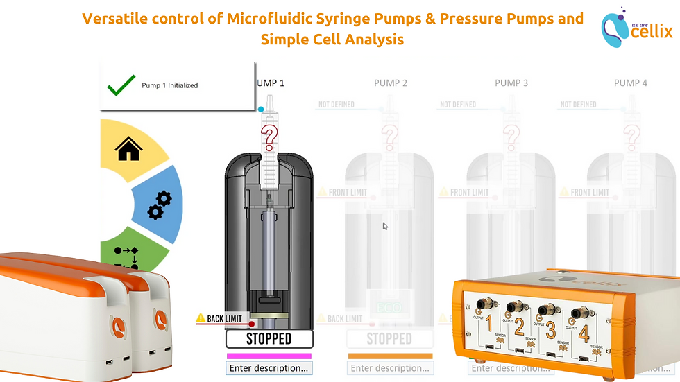
SmartFlo is a versatile software for control of Cellix's ExiGo syringe pumps and UniGo or 4U pressure pumps. You don't have to choose between syringe pumps and pressure pumps; you can have both in one set-up, smartly controlled by one seamless software, SmartFlo.
How to use Cellix's SmartFlo Software with the UniGo or 4U pump?
The UniGo or 4U pumps do not require an initialisation. A manual flow rate or a custom flow profile can be applied and executed directly after booting up.
This article covers the following topics - you can read through all of them or click on the links to jump to the topic which interests you:
1. Setting the feedback
The recommended option is to use Flow rate as a feedback parameter for your UniGo or 4U pump. However, advanced users have the option to switch to a pure pressure control by selecting pressure as a feedback parameter. [1]
To change the feedback parameter:
In the Manual Tab, click on SETTINGS
In the settings window, click on the Advanced settings Icon
Click on Flow/ Pressure to switch between Flow and Pressure
Click on UPDATE
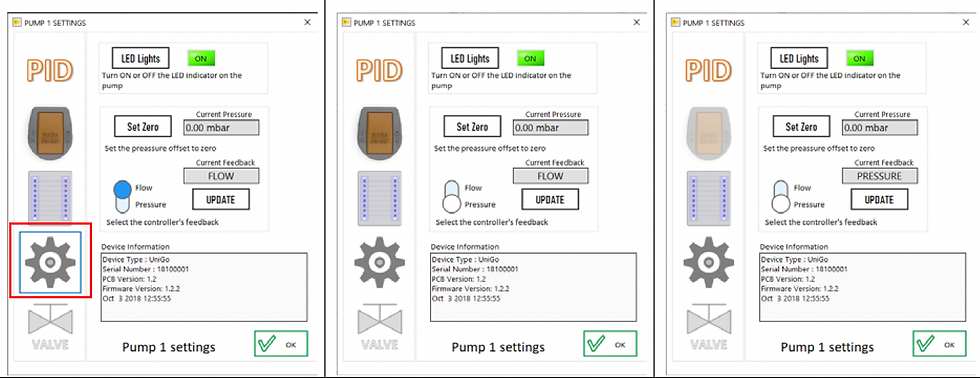
Note that when pressure is selected as a feedback, all the units are automatically updated from nL/min to mbar.
2. Manual mode: How to set the flow rate or pressure?
Depending on the selected feedback parameter, the set-point can be specified in flow rate (L/min) or pressure units (bar):

Click in the flow rate indicator
Set the desired flow rate value. Click✔️ to accept the changes
The flow rate you set should now appear now within the flow rate indicator. Press SET in order to update the pump flow rate set point.
Once the flow rate has been set, press the RUN button to start the assay.

Click in the pressure indicator
Set the desired pressure value. Click ✔️ to accept the changes
The pressure set-point should appear now within the indicator. Press SET in order to update the pump’s set point.
Once the set-point has been set, press the RUN button to start the pump.
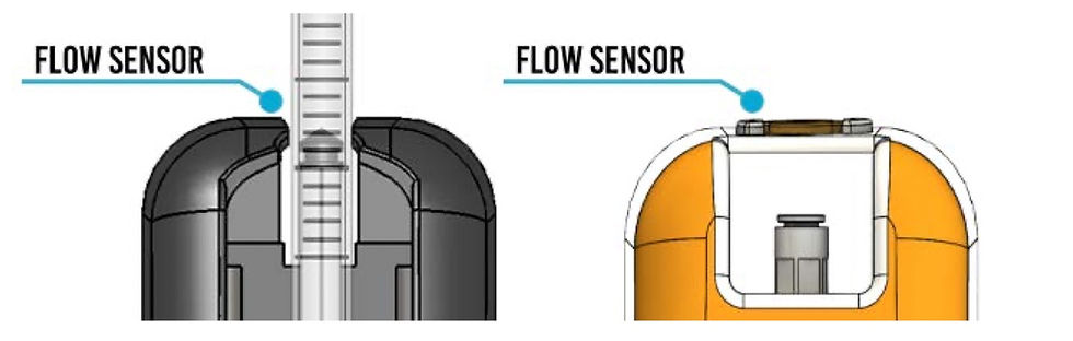
3. Flow Sensor: Visualizing the flow rates
The performance of the pump(s) can be significantly increased by using a flow sensor to obtain real-time flow rate feedback. The flow sensor can be connected to ExiGo pump (optional) and it is compulsory for UniGo/4U pumps.
Each flow sensor is plug-and-play; therefore it can be connected to the pump(s) at any moment.
Once the sensor is connected and recognized by the pump, a “Flow Sensor” indicator will appear in SmartFlo.
Immediately after plugging-in the flow sensor, the real time flow rate measurements will appear within the Manual Tab.

It is possible to record the measured flow rates within a particular assay and when running in manual mode. Please refer to section 10 for more details.
When running a UniGo or 4U pump, it is possible to switch to pressure readings. Just switch between flow rate and pressure by clicking Flow/Pressure.
4. Setting the PID parameters
In order to get the best performance and accuracy of the ExiGo/UniGo/4U pumps as well as a fast dynamic response, the PID controller must be turned on.[2]

5. How to tune in the PID?
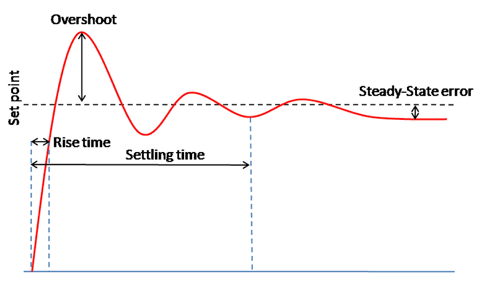
Set all parameters to 0.
Increase P and change the set point until the dynamic response of the pump is fast enough without oscillating.
Increase gradually I value in order to minimize the Steady-State error. Integral parameter can be any value between 0 and 1 but it is very sensitive and may cause the system to oscillate. Therefore it is recommended to start using a value of 0.001. A value over 0.1 will probably lead the system to become unstable.
In case of a large overshoot when changing the set point, increase the D value gradually until the optimal ratio overshoot/response time is achieved. However, a large value of D may slow down the dynamic response of the system.
6. Program mode: Defining a custom flow profile
It is possible to program a pump with a custom flow profile in order to have a precise control of the flow rates and duration of a certain experiment.
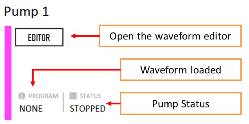
Click EDITOR in order to open the Waveform Editor.
Enter your waveform elements
Click button to program the selected pump.
Repeat steps 1 to 3 for the remaining pumps.
Click RUN to run a particular pump or RUNALL to run all the programmed pumps simultaneously.
7. Waveform Editor
The waveform Editor allows you to create a custom flow profile for your pump(s).

You can add 4 different elements to your waveform:
Constant Flow/Pause
Ramp
Pulse wave
Sine wave


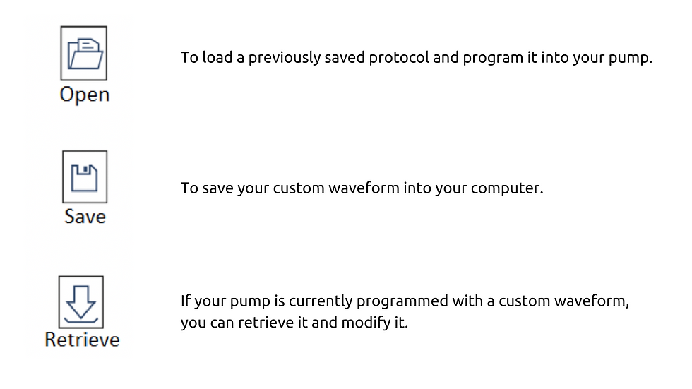
8. Open/Save custom waveforms
You can load and/or save a custom waveform into your PC using the following buttons:
9. Recording the flow rates/pressures data
It is possible to record the measured flow rates/pressures during an experiment in a log file. In order to generate the log file, please complete the following steps:

In the manual section click Record Data to start recording the data.
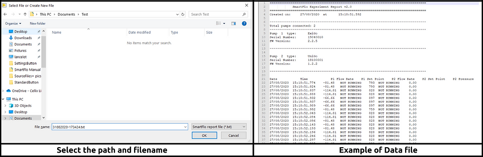
A pop-up window will appear. Enter your filename and destination.
Click OK
To finish the data recording, press Record Data again
The created log file will have a format similar to the following example
10. Flow sensor coefficients
Cellix’s flow sensors are calibrated for aqueous solutions by default. Running other liquids such as oils, IPAs etc, through the sensor using the default coefficient would result in an incorrect flow rate reading. However it is possible to add a custom calibration coefficient to correct the reading.[3]
To add a custom calibration coefficient:
In the Manual Tab, click SETTINGS.
In the settings window, click on the Sensor settings Icon.
Open the Coefficients manager.
Click NEW.
Enter the name, media and a description of the media.
Select the type of coefficient Fit type (lineal or polynomial).
Type in the coefficients.
Click Save.
Once your coefficient has been created, it will be available in the Coefficients manager window.
To select the created coefficient, close the Coefficient Manager and select it on the Sensor settings window.
Select the created coefficient and click UPDATE.

References
Cellix recommends to keep flow rate as a feedback parameter. Using pressure control only might lead to having a different flow rate than expected as it would depend on the fluidic resistance of your setup, viscosity of the media, etc.
If controlling an ExiGo pump, the PID can only be turned on when a flow sensor is connected. If you purchased an ExiGo pump without a flow sensor you can still use the pump without the PID controller. Please contact Cellix if you wish to purchase one.
Warning: Introducing the wrong coefficient might lead to an incorrect flow measurement and cause damage to your pump and/or your setup. Please, contact Cellix for more information on how to use custom calibration coefficients.
