
Flow Sensors
For Microfluidic Syringe and Pressure Pumps


CLOSED-LOOP FEEDBACK: Flow sensors provide active feedback and precise flow control.
MODULAR: suitable for use with ExiGo syringe pumps, UniGo and 4U pressure pumps so you can mix-and-match syringe and pressure pumps giving greater flexibility for your microfluidic set-up.
FLOW RANGES: 7µL, 80µL and 1mL sensors available.
LOW DEAD VOLUME: 1.5µL, 5µL & 25µL dead volume for 7µL, 80µL & 1mL sensors, respectively.
HOW DOES IT WORK?
Measurement Principle
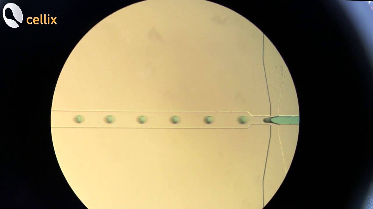
Flow sensors are based on the thermal mass flow measurement principle. Each flow sensor includes a microchip with a microscopic heating element and 2 temperatures sensors on each side of the heating element. They are built into the exterior of the flow channel wall, isolating them from the liquid. The heating element adds a tiny amount of heat to the liquid. As the liquid flows through the sensor, it carries the "heat cloud" downstream, as seen in the image.

The temperature sensor measures the temperature upstream and downstream of the heating element through the wall without touching the liquid. Using the difference in upstream and downstream temperature, the microchip generates a linearised, fully calibrated digital output signal.
Key Benefits of this type of flow sensor include high-speed measurement (microsecond range); easy integration with standard connectors, and straight, unobstructed flow channels which contain no moving parts.

Unlike standard syringe pumps, response time down to 50ms

Down to nL/min range - active feedback with flow sensors.

Program any combination of constant, ramp, sine and step.
Unlike standard syringe pumps, response time down to 50ms
DOWNLOADS


How to use your flow sensor: Easy-to-use SmartFlo Program
SMARTFLO: Common commands for UniGo and 4U Pressure Pumps
SmartFlo is the software program used to program ExiGo syringe pumps and Unigo & 4U pressure pumps. You can use SmartFlo to control the PID settings for your microfluidic pump.
Proportional (Kp): The proportional gain defines how quickly the system will change its output to reduce the existing error (Flow rate set point minus current flow rate). Therefore, the proportional parameter will increase the speed of the control system response. However, if the proportional value is too large, the system will begin to oscillate. Using P parameter on its own may lead to a Steady-State error (offset) between desired flow rate and current flow rate.
Integral (Ki): The integral term sums the instantaneous flow rate error over time and gives the accumulated offset that should have been corrected. Thus, its main purpose is to drive the flow rate Steady-State error to zero. A large value of the Integral parameter may cause the system to overshoot the set point value and even oscillate.
Derivative (Kd): The derivative term is proportional to the rate of change of the system output (pump flow rate). Therefore it “predicts” the system behaviour decreasing the system output if the flow rate is changing rapidly. This parameter helps to reduce overshoot and settling time but an incorrect value may cause the system to become unstable.

How to tune the PID settings:
1. Set all parameters to 0.
2. Increase P and change the set point until the dynamic response of the pump is fast enough without oscillating.
3. Increase gradually I value in order to minimize the Steady-State error. Integral parameter can be any value between 0 and 1 but it is very sensitive and may cause the system to oscillate. Therefore it is recommended to start using a value of 0.001. A value over 0.1 will probably lead the system to become unstable.
4. In case of a large overshoot when changing the set point, increase the D value gradually until the optimal ratio overshoot/response time is achieved. However, a large value of D may slow down the dynamic response of the system.

Flow Sensor Coefficients:
Cellix’s flow sensors are calibrated for aqueous solutions by default. Running other liquids such as oils, IPAs etc, through the sensor using the default coefficient would result in an incorrect flow rate reading. However it is possible to add a custom calibration coefficient to correct the reading.[1]
Warning: Introducing the wrong coefficient might lead to an incorrect flow measurement and cause damage to your pump and/or your setup. Please, contact Cellix for more information on how to use custom calibration coefficients.
Create Custom Calibration Coefficients for Different Sample Types:

Click Settings, Click Flow Sensor icon and open Coefficients manager.

Click New+

Select from the Flow Sensor settings window.
Click Settings, Click Flow Sensor icon and open Coefficients manager.
Connecting your Flow Sensor
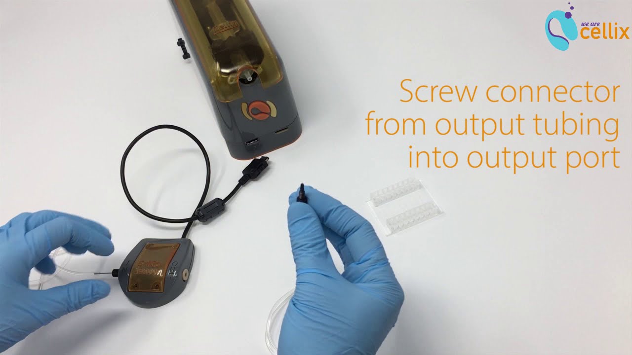
It is easy to connect your flow sensor to your microfluidic pump - this is done by standard connectors. We use the same connectors (1/32" black nut & ferrule) for 7.0µL and 80uL sensors. For 1.0mL sensors, we use ¼” - 28 black PPS nut, flangeless. See the following table as a guide for which connectors and tubing are used for 7.0µL, 80uL and 1.0mL sensors.


RELATED PRODUCTS

ExiGo Syringe Pump

UniGo Pressure Pump

4U Pressure Pump

Tubing & Connectors


